Driving a Character LCD using PIC24 Enhanced Parallel Master Port
Traditionally, Toshiba HD44780-compatible alphanumeric LCD displays are driven by bit-banging bus signals combined with long delays between sending commands and data. In many cases, this method is good enough. However, there are situations where extra CPU cycles are not available, and a more efficient method of driving the display is needed. I’m currently working on a design involving very fast USB exchanges combined with occasional LCD output, and I’ve developed a solution that works very well for me. I’m sharing it in the hope that fellow developers will find it useful.
HD44780 displays have been around for a long time. The internet offers plenty of posts about them, code samples, and even a Wikipedia article. My favorite introductory resource on the topic is Dincer Aydin’s LCD Info page.
PIC24 16-bit microcontrollers from Microchip have also been around for some time. They are cheap and powerful, and the Microchip C30 compiler (a free version is available) is quite good. However, they are not as popular as their 8-bit counterparts from Microchip and Atmel, so good PIC24 resources are relatively scarce. This book contains a comprehensive course on the PIC24 family and its peripherals.
Since I’m trying to minimize the CPU time spent driving the LCD, let’s first talk about timing in general. When developing for the HD44780, we need to consider three different types of timing.
The first is the timing of the display itself—the screen we see. LCD glass is very slow. When we attempt to update the screen faster than, say, twice a second, the symbols become blurry and pale. The fastest display in my collection still looks OK when updated at a 4 Hz rate (every 250 ms), while most others are twice as slow.
On the other hand, display data bus timing is much faster. To write to the display, we first need to set the RS, RW, and data lines, wait briefly, assert the E line, wait again, and then de-assert it. If we’re reading from the display, we also need to wait a bit more after de-asserting E before we can read the data on the bus. The total bus cycle length is around 2.5 µs, which is about 200,000 times shorter than the update rate of typical LCD glass. This time is short, but the MCU is still faster - a PIC24F clocked at 32 MHz has an instruction cycle of 62.5 ns and can execute about 40 instructions in 2.5 µs. Therefore, no matter how simple it seems, it’s preferable not to bit-bang the bus since most of the time will be spent waiting.
The third timing to consider is command execution time. All but two LCD commands have a stated execution time of 40 µs. The two slower commands - Clear and Home - require 1.64 ms to complete. These are datasheet values; in practice, fast commands on a modern display may complete in as little as 10 µs, while slow commands on an older display can take as long as 3.5 ms, depending on the age and specific “HD44780-compatible” controller used. This execution time is still about 100 times faster than the glass.
To drive my LCD efficiently, I did the following:
-
Assigned LCD pins to be driven using the Enhanced Parallel Master Port (EPMP) peripheral available in the PIC24FJ256GB206 part I’m using. This allows starting (and completing) the bus cycle by simply “writing” to a certain memory address.
-
Created a circular buffer for commands and data to be sent to the LCD. This allows asynchronous access—the application places a string of characters into the queue, and the LCD outputs them at its own pace. To use the same byte-wide queue for both commands and data, I insert a special “flag” character before a command.
-
Wrote a timer interrupt routine to read the queue, send commands/data, and wait the necessary amount of time between commands. Using the timer allows the application to continue executing during wait periods. The timer routine also adjusts the delay based on the type of the last command sent to the LCD.
The rest of this article discusses the implementation details. For demonstration purposes, I wrote a simple test application, the most interesting parts of which will be explained below. The code for the application was largely copied and pasted from another project, so the choice of MCU, crystal speed, and timer settings may appear somewhat arbitrary.
I’ll start by explaining the EPMP portion. This peripheral allows the creation of parallel memory interfaces with different bus and data sizes, as well as control signals with programmable timings. It is similar to the older PMP (Parallel Master Port) peripheral. An example of a PMP-driven LCD is found in Microchip’s ever-popular Explorer 16 board. Another example is presented in Lucio Di Jasio’s book. In my application, the pinout is very similar to those sources: the EPMP PMA line is used for RS, PMRD is used for RW, and PMWR is used for E. For simplicity, I’m using an 8-bit LCD interface and an 8-bit EPMP configuration.
Unlike PMP, EPMP uses extended memory space to access the bus. This is how the definitions of the LCD command and data registers look:
//address allocation for LCD registers
__eds__ uint8_t __attribute__((noload, section("epmp_cs1"), address(CS_BASE))) LCDCMD __attribute__((space(eds)));
__eds__ uint8_t __attribute__((noload, section("epmp_cs1"), address(CS_BASE))) LCDALIGN __attribute__((space(eds)));
__eds__ uint8_t __attribute__((noload, section("epmp_cs1"), address(CS_BASE))) LCDDATA __attribute__((space(eds)));
First line defines LCD command register, third line defines LCD data register and the second line is used to align data register to 16-bit word boundary. This is done so that RS will clear while accessing LCDCMD and set while accessing LCDDATA – PIC24 is a 16-bit MCU and each memory address addresses 2-byte word.
Now, let’s program the EPMP registers in order of appearance in corresponding PIC24F Familiy Reference Manual AKA FRM, the first being PMCON1:
PMCON1bits.ADRMUX = 0;      // address is not multiplexed
PMCON1bits.MODE = 3;        // master mode
PMCON1bits.CSF = 0;         // PMCS1 pin used for chip select 1, PMCS2 pin used for chip select 2
PMCON1bits.ALMODE = 0;      // "smart" address strobes are not used
PMCON1bits.BUSKEEP = 0;     // bus keeper is not used
PMCON1bits.IRQM = 0;        //interrupt at the end of of rd/wr cycle
The bit settings are self-explanatory. Basically, I set non-multiplexed address lines and master mode of the module.
The PMCON2 register can be left at default settings. The PMCON3 looks like this:
PMCON3bits.PTWREN = 1;      // enable write(rd/WR) strobe port
PMCON3bits.PTRDEN = 1;      // enable read(enable) strobe port
PMCON3bits.AWAITM = 0;      // set address latch pulses width to 1/2 Tcy
PMCON3bits.AWAITE = 0;      // set address hold time to 1/4 Tcy
Here I enable READ and WRITE signals and set address latch signal (which is not used) delay to the minimum. Later, I will combine READ and WRITE to a single RW and make E(NABLE) out of WRITE.
The PMCON4 configuration is very simple:
PMCON4 = 0x0001; // PMA0 address line is enabled
Here I enable a single address line which will serve as LCD RS signal switching between command and data registers.
The PMCS1CF register defines the behaviour of lines used as LCD RW and E lines. They are tied to EPMP CS signal so we need it active even though we don’t need CS to drive an LCD.
PMCS1CFbits.CSDIS = 0;     // enable CS function
PMCS1CFbits.CSP = 1;       // CS1 polarity
PMCS1CFbits.CSPTEN = 0;    // disable CS port
PMCS1CFbits.BEP = 1;       // byte enable polarity
PMCS1CFbits.WRSP = 1;      // write strobe polarity - enable active high
PMCS1CFbits.RDSP =1;       // read strobe polarity, READ high, WRITE low
PMCS1CFbits.SM = 1;        // read/write and enable strobes
PMCS1CFbits.PTSZ = 0;      // data bus width is 8 bit
Even if CS signal is not used we still need to configure it since READ/WRITE and ENABLE depend on it. CSDIS enables the CS function and CSPTEN disables the CS pin. The part I’m using have it combined with upper PMA address which has already being disabled in PMCON4. The CS is separate on 100-pin parts so I’m disabling it second time here just in case. BEP can be any value since it’s not used. WRSP sets E polarity (active high), RDSP sets 0 for write and 1 for read to be used as LCD RW line. SM combines READ and WRITE into a single pin and sets separate ENABLE. Finally, PTSZ sets data bus width to 8 bits.
PMCS1BS = (CS_BASE>>8); // CS1 start address
PMCS1BS sets starting extended memory address for EPMP. An attentive reader may have noticed that this is the same address used in LCDCMD and LCDDADA definitions. I’m using the 0x20000 address which is the default; technically, in this case I don’t need to set PMCS1BS since it contains the same value at power-on – I just wanted to show how it’s done.
Last interesting piece of EPMP configuration is timing of all important signals. The necessary bits are contained in PMCS1MD register, as follows:
PMCS1MDbits.DWAITB = 3;      // time from RS,RW to E
PMCS1MDbits.DWAITM = 0x08;   //E strobe length - 450ns by spec
PMCS1MDbits.DWAITE = 3;      //time from E to valid data
These times were chosen conservatively. In my experience, for modern displays they can be made much shorter and even set to zero. The speed advantage is very small and only appears when LCD reads are performed.
The last thing to do is to enable the EPMP module:
PMCON1bits.PMPEN = 1; // enable the module
After this is done, writing to an LCD is as simple as doing LCDCMD = command for commands or LCDDATA = data for data. Since a bus cycle is longer than a single instruction cycle and EPMP has no buffer in master mode we would have to wait between issuing consecutive writes. However, since we will also need to wait for the LCD to digest what’s been sent to it and this wait time is substantially longer than a bus cycle, we don’t need to worry about that.
Reading the LCD does involve waiting since the data become available on the bus at the end of a cycle. I don’t use LCD read in my code but here is a short example borrowed from the FRM:
value = LCDCMD;         //dummy read
while(PMCON2bits.BUSY); // wait for the end of bus cycle
value = PMDIN1;         // real read
First line initiates the bus cycle, second line waits for the bus cycle to complete, last line reads the value from the bus at the falling edge of E. This example reads from the command register and can be used to check BUSY flag. Also, if times in PMCS1MD are all set to zero wait states the bus cycle will take one instruction cycle and checking EPMP busy flag won’t be necessary.
To feed the data to LCD I’m using a simple one-way circular buffer AKA queue, defined like that:
//LCD buffer size - must be a power of 2
#define LCD_TX_BUFSIZE 256
#define LCD_TX_BUFMASK ( LCD_TX_BUFSIZE - 1 )

#if ( LCD_TX_BUFSIZE & LCD_TX_BUFMASK )
#error LCD Tx Buffer size is not a power of 2
#endif

//LCD buffer
uint8_t LcdTx_Buf[LCD_TX_BUFSIZE];
uint8_t LcdTx_Head;
volatile uint8_t LcdTx_Tail;
To make queue management easier the size must be a power of 2. The size of 256 saves couple instruction cycles; if memory size is more important the buffer size can be decreased. LcdTx_Head is moved by a producer of the data and LcdTx_Tail is moved by the consumer, as will be explained later in the article. LcdTx_Buf is the buffer itself. Very detailed explanation of this type of circular buffer is given in Fred Eady’s excellent Networking and Internetworking with Microcontrollers book on pages 51-70.
I will now explain the timer interrupt service routine (ISR) which consumes the queue and sends data to LCD using EPMP. The routine gets called each time the timer overflows. Two distinctive time intervals are used – one for fast commands and data and the second one for slow commands Clear and Home. When the queue is empty the timer is stopped since there is no reason to run it anymore. When data is placed into the queue the timer is started again. Commands in the queue are preceded by a special “flag”: the ISR tracks that and sends data to either command or data register. The following (rather long) listing demonstrates how all this is coded.
//Timer interrupt
#define TIMER3_ISR_PRIO 1
void  __attribute__((__interrupt__, auto_psv)) _T3Interrupt(void)
{
 static uint8_t state = 0;

    _T3IF = 0;    //clear interrupt flag

    LcdTx_Tail++;

#if LCD_TX_BUFMASK < 255
        LcdTx_Tail &= LCD_TX_BUFMASK;
#endif

    switch( state ) {

    case 0:    //read byte, send data

        if( LcdTx_Buf[ LcdTx_Tail ] == CMDFLAG ) {    //next byte is a command

            TMR3 = PR3 - 20;    //shorter cycle. Must be set longer than the execution time of the rest of the ISR

        state = 1;
      }//if( LcdTx_Buf[ LcdTx_Tail ] == CMDFLAG...
      else {

        LCDDATA = LcdTx_Buf[ LcdTx_Tail ];    //send data

        PR3 = BSP_TMR3_PER_SHORT;
      }
      break;

  case 1:    //send command

    LCDCMD = LcdTx_Buf[ LcdTx_Tail ];    //send command

        if( LcdTx_Buf[ LcdTx_Tail ] < 4 ) {  //slow command

        PR3 = BSP_TMR3_PER_LONG;

      }
      else {

        PR3 = BSP_TMR3_PER_SHORT;

      }

      state = 0;

      break;

    }//switch( state...

    if( LcdTx_Head == LcdTx_Tail ) {    //stop the timer

        T3CONbits.TON = 0;

    }
}
The following piece of code shows the initialization of this timer:
/Setup timer 3 for LCD
T3CON  = 0x0000;                     /* Use Internal Osc (Fcy), 16 bit mode, no prescaler */
PR3    = BSP_TMR3_PER_SHORT;         /* set the period */
TMR3   = PR3 - 1;                    /* one count before interrupt */
_T3IP  = TIMER3_ISR_PRIO;            /* set Timer 3 interrupt priority */
_T3IF  = 0;                          /* clear the interrupt for Timer 2 */
_T3IE  = 1;                          /* enable interrupt for Timer 2 */
//we don't want to start this timer yet
The timer will be turned on when the first byte is placed into the queue and since at this time the LCD is ready to take it the TMR3 is set one cycle less than PR3 so the interrupt will happen almost immediately.
We will now take a look at the producer part – what needs to happen in the application to place a byte in the LCD queue. This is done by LcdSendByte() function:
/* Places a byte to the LCD queue. Can be used to send data */
void LcdSendByte(uint8_t byte) {
 uint8_t tmphead = LcdTx_Head + 1;

#if LCD_TX_BUFMASK < 255
 tmphead &= LCD_TX_BUFMASK;
#endif

   while( tmphead == LcdTx_Tail );  //this line blocks - keep buffer large enough

   LcdTx_Buf[ tmphead ] = byte;

   LcdTx_Head = tmphead;

   T3CONbits.TON = 1;    //start the timer in case it was previously stopped
}
This function can be used to send character data to the LCD. To send a command we need to insert a flag before it. The LcdSendCmd() function does just that:
/* Places a command flag to the LCD queue followed by a byte */
void LcdSendCmd(uint8_t cmd) {

  LcdSendByte( CMDFLAG );   //insert command flag symbol
  LcdSendByte( cmd );

}
We now have everything necessary to use the LCD. The following is a main() routine which first initializes both MCU and LCD and then fills first four screen positions with BSD-stype “rolling stick” character. Note that initialization commands are placed directly into LCDCMD – this is because during initialization wait time between commands must be made much larger.
int main( void )
{
//initialization commands for standard 16x2 LCD
#define FUNC_SET  LCD_FUNCTIONSET|LCD_8BITMODE|LCD_2LINE|LCD_5x8DOTS
#define DISP_CTRL LCD_DISPLAYCONTROL|LCD_DISPLAYON|LCD_CURSOROFF|LCD_BLINKOFF
#define ENTRY_MODE LCD_ENTRYMODESET|LCD_ENTRYLEFT

 const uint8_t lcd_init_seq[] = { FUNC_SET, DISP_CTRL, LCD_CLEARDISPLAY, ENTRY_MODE, 0 };   //initialization sequence
 const uint8_t* lcd_init_p = lcd_init_seq;  //pointer to the first element
 const uint8_t rollchar[4] = {'/','-','\\','|'};
 uint8_t roll_idx = 0;
#define ROLL_IDX_MASK 0x03

    MCU_init();

    while( *lcd_init_p ) {  //power-on display initialization

        __delay_ms( 30 );

        LCDCMD = *lcd_init_p++; //place a byte directly on the LCD bus

    }

    while( 1 ) {    //output rolling characters in the first 4 posirions of the display

        uint8_t i;

        LcdSendCmd( LCD_RETURNHOME ); //Home the screen - slow command

        for( i = 0; i < 4; i++ ) {

            LcdSendByte( rollchar[ roll_idx ] ); //fast command

        }

        roll_idx++;
        roll_idx &= ROLL_IDX_MASK;

        __delay_ms( 1000 );

    }//while( 1 )
}//main
The GitHub repo mentioned in the beginning contains a single file with the program. In order to use it you need to compile it with Microchip C30 compiler (I used version 3.31) and load it to the PIC24 micro. You will also need to connect the LCD, the pinout depending on a part. For PIC24FJ256GB206 the pinout is this:
- Pin 30 – RS
- Pin 53 – RW
- Pin 52 – E
- Pin 60 – D0
- Pin 61 – D1
- Pin 62 – D2
- Pin 63 – D3
- Pin 64 – D4
- Pin 1 – D5
- Pin 2 – D6
- Pin 3 – D7
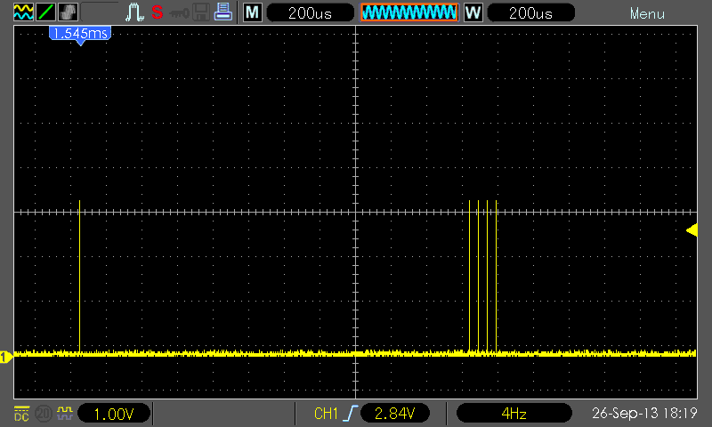
The program may work on Explorer 16 board equipped with EPMP-capable MCU. The title picture shows the oscilloscope screenshot of E strobe when the program is running – Home, long wait then 4 characters.
The program can be modified for different CPUs and crystal speeds. Also, it is possible to fine tune the times. Simply change the intervals for short/long commands and see if the screen still looks good. The definitions look like this:
//timer period for fast and slow commands
#define BSP_TMR3_PER_SHORT  799     //Timer3 period for fast commands
//#define BSP_TMR3_PER_SHORT 2000
#define BSP_TMR3_PER_LONG       35000   //Timer3 period for slow commands
//#define BSP_TMR3_PER_LONG 55000
It should be noted that total execution time (or CPU time) is the same in all cases so it is not necessary to set timer period precisely. In most cases, one or the other set of numbers will be good enough.